About Us


Product Details
Hardware Features:
1. There are two hardware versions: Internal PCBA Antenna(VM300-L) and external antenna (VM300-H)
2. Two external antenna RF female sockets (only VM300-H)
3. Comes with a button to restore factory parameters
4. Wide power supply working voltage: DC5V--24V
5. Support power input over-voltage protection function (automatic power-off when the power supply voltage exceeds 29V)
6. Main chip: MT7620N, 580MHz
7.32Mb SDRAM, can be expanded to 64Mb; 4Mb SPI Flash, can be expanded to 16Mb (Byte)
8. WiFi working frequency band: 2.4GHz, 2T2R dual antenna, 300Mbps transmission rate
9. Support 1--14 WiFi channels
10. Rated average power consumption <2W
11. Module RF output power 14.5dbm/16dbm (two gear output power optional)
12. Support temperature compensation and frequency stabilization technology (TAFC) to ensure the stability of WiFi signal.
13. Support 802.11b/g/n mode
14. Working environment temperature: -20℃-- 55℃
Function Features:
1. Two software-controllable working modes: router mode, bridge + repeater mode
2. Support smart transparent bridge mode, and support AP Client and AP Station at the same time
3. Support VDNS technology, domain name can be used to log in to the configuration page in bridge mode
4. The relevant parameters of the device can be configured through the WEB page configuration or the VCC mobile phone APP
5. The software can adjust two levels of WiFi RF output power (14.5dbm/16dbm)
6. Support SSA 1.2 version signal strength remote center alarm protocol
7. Support VONETS-Configuration Management Protocol V2.3 (confidential)
8. Support transparent transmission of serial and network data (VONETS-UART_UDP or TCP data forwarding instructions 3.0)
9. Online software upgrade
Specification Parameters
Female Interface Subinterface | Hardware pin definition (PIN) | Description | ||
PA | PB | PC | ||
VIN+ | 6 | 6 | DC5V--15V, the input voltage ripple is required to be less than 100mV, otherwise it will affect the WiFi transmission performance | |
GND | 5 | 5 | 8、4 | Module ground |
LAN | 1:RX+ | 1:RX+ | PA and PB are parallel interfaces, but they are actually the same port (only one can be used at a time) | |
LAN Port Status Indication Output | 3 | 1. MOS tube open circuit output, built-in 330Ω current limiting resistor 2. Output current: 10mA | ||
WAN Port Status Indication Output | 2 | 1. MOS tube open circuit output, built-in 330Ω current limiting resistor 2. Output current: 10mA | ||
WiFi Status Indication Output | 1 | 1. MOS tube open circuit output, built-in 330Ω current limiting resistor 2. Output current: 10mA | ||
Reset Signal Input | 5 | After the module works normally, keep the low level for more than 3 seconds, the module will restore the factory parameters (less than 0.6V is the low level) | ||
UART-TX | 6 | TX signal line of UART used for serial port transparent transmission, TTL level output | ||
UART-RX | 7 | RX signal line of UART used for serial port transparent transmission, TTL level input | ||
Power enable pin | 0 | Module power enable control pin, the default state is power enable. If the control voltage of this pin is less than 1V, the module power supply is off | ||
Standard RJ45 female socket pin definition reference | 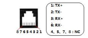
| |||

Related Downloads
Click: VM300-L And VM300-H Module Specifications v9.0
Mall Link
Amazon Shop:


Aliexpress Shop: